
Solder Paste Printer Guide: Process, Setup and Selection
A solder paste printer aligns a PCB with a stencil and transfers controlled deposits of solder paste onto component pads. Print quality depends on stencil design, paste behavior, board support, alignment, squeegee pressure and speed, separation, and cleaning. Select a printer around the product process window, not cycle time alone.
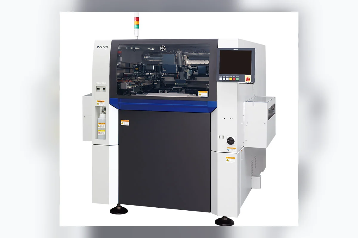
# Solder Paste Printer Guide: Process, Setup and Selection
A solder paste printer aligns a PCB with a stencil and transfers controlled deposits of solder paste onto component pads. Print quality depends on stencil design, paste behavior, board support, alignment, squeegee pressure and speed, separation, and cleaning. Select a printer around the product process window, not cycle time alone.
Printing Cycle and Controls
The printer loads and clamps the PCB, reads fiducials, supports the board, rolls paste across stencil apertures, separates the stencil and cleans its underside when required. JUKI’s RP-2 page illustrates current functions including paste replenishment, roll monitoring and aperture inspection.
| Control | Typical effect when wrong |
|---|---|
| Alignment | Deposits shift from pads |
| Pressure | Incomplete fill, scooping or stencil wear |
| Speed | Poor aperture filling or unstable rolling |
| Separation | Smear or incomplete release |
| Board support | Local variation and board flex |
| Cleaning | Blocked apertures or underside contamination |
Settings interact. More pressure may hide a blocked aperture while accelerating wear.
Common Defects
- Insufficient paste: check stencil, paste condition, pressure, speed and release.
- Bridging: check stencil underside, gap, slump and separation.
- Offset: check fiducials, clamps, board stretch and support.
- Volume drift: check paste roll, exposure time, cleaning and stencil wear.
- Local variation: check support pins, warpage, gasketing and aperture design.
SPI trends should be grouped by location and time so engineering can separate design/tooling patterns from material or machine drift.
Selection and Acceptance
Confirm board and stencil range, accuracy, support method, cleaning modes, paste control, traceability, cycle time and SPI feedback. Test the most difficult board and measure deposits with SPI. Include program creation, changeover, cleaning and sustained production.
Fuji states that its printer lineup uses pressure control and cleaning to address board warpage and material variation. Features like these must be demonstrated on the intended product. See Fuji printers.
FAQ
Can SPI correct a bad print?
SPI can trigger process corrections; it does not repair paste already printed on a defective board.
What belongs in a printer RFQ?
Board drawings, stencil frame, smallest apertures, paste, output, changeovers, support, inspection and traceability.
Primary Sources
Need help identifying an SMT replacement part?
Send the machine model, part number and clear label photos. SMTBase will review the available sourcing options.
Contact SMTBase →