
Guía sobre boquillas SMT: selección, limpieza y sustitución
Learn how to select an SMT nozzle, diagnose pickup faults, clean and inspect nozzle tips, and provide the right details when ordering a replacement.
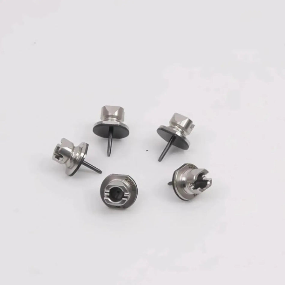
An SMT nozzle is the replaceable tool on a placement head that uses vacuum, and sometimes positive air pressure, to pick, hold, move, and release an electronic component. Correct nozzle selection depends on the machine and head interface as well as the component's pickup surface, dimensions, weight, material, and required placement force.
A nozzle is small, but its condition can affect pickup rate, component recognition, placement stability, and board quality. Repeated mispicks are not proof that the nozzle is faulty, however. Feeders, vacuum circuits, component packaging, program data, and head condition can produce similar symptoms.
Respuesta breve: Select an SMT nozzle by exact machine and head family, nozzle part number, component geometry, pickup area, mass, surface condition, vision requirements, and placement force. Inspect flow, tip condition, sliding action, and identification after cleaning. Replace a nozzle when damage, wear, deformation, blockage, or failed inspection makes reliable pickup impossible.
What Does an SMT Nozzle Do?
The nozzle forms the physical connection between the placement head and the component. During a normal cycle it descends to the feeder, seals against the component, holds it under vacuum, carries it through recognition, places it into solder paste, and releases it.
JUKI's explanation of SMT equipment describes the nozzle as the element that picks and places components while the head carries them to their placement locations. See JUKI's SMT equipment overview.
A suitable nozzle must perform several tasks at once:
- make a stable vacuum seal;
- avoid damaging the component;
- leave package edges or leads visible when the vision method requires them;
- resist unwanted rotation or tilt during acceleration;
- release the component cleanly at the programmed height and force;
- fit the spindle, changer, identification system, and software library.
Main Parts of a Placement Nozzle
Nozzle construction differs by platform, but common elements include:
| Element | Función | Typical issue |
|---|---|---|
| Tip or pickup face | Contacts the component | Wear, chips, scratches, contamination, deformation |
| Vacuum bore | Carries vacuum to the tip | Dust, adhesive or flux blockage, restricted flow |
| Shaft or body | Locates the nozzle in the spindle | Wear, bending, incorrect dimensions |
| Sliding mechanism | Allows controlled vertical compliance on some designs | Sticking, contamination, spring or seal damage |
| Reflector or recognition feature | Helps the machine identify or measure the nozzle | Discoloration, damage, dirt, wrong geometry |
| ID code, RFID or marking | Identifies nozzle type or individual nozzle | Unreadable code, wrong data, missing tag |
| Retention feature | Holds the nozzle in the head or changer | Wear, incorrect fit, dropped nozzle |
When requesting a spare, photograph the complete nozzle and each marking. A tip-only match is not enough because the body, length, reflector, bore, or retention feature may differ.
SMT Nozzle Types
Nozzles are often grouped by the component they handle, but the manufacturer's nozzle code remains the safest identification method.
Round vacuum nozzles
Round tips are common for chip components and packages with a flat central pickup area. The tip diameter must fit within that area while providing enough holding force.
Rectangular or shaped nozzles
A shaped pickup face can provide better support for rectangular, long, narrow, or asymmetrical components. It may also help control rotation under rapid head movement.
Large-component nozzles
Large or heavy components may require a wider contact area, increased flow, a special material, slower acceleration, or more than one pickup point. Check the head's allowable mass and moment as well as nozzle capacity.
Soft-tip or low-impact nozzles
Rubber, compliant, or specially designed tips may be used for fragile surfaces, lenses, shields, and packages that could be marked or damaged. Material compatibility and wear need close control.
Grippers and custom tools
Some odd-form parts have no suitable vacuum surface. A mechanical gripper or a custom tool may be necessary. Provide a component drawing, 3D data where available, mass, center of gravity, packaging, and placement requirements.
How to Select the Correct SMT Nozzle
Start with the machine-approved nozzle table, then confirm the actual component. A nozzle that can lift the part during a bench test may still be unsuitable at production speed.
1. Confirm machine and head compatibility
Record the machine brand, full model, head type, spindle type, software version if relevant, and current nozzle number. Machines within the same brand can use different nozzle families.
2. Measure the usable pickup surface
The package outline is not the same as the pickup area. Avoid terminals, vents, labels, uneven moulding, lenses, and surfaces that cannot form a seal. For connectors and odd-form parts, confirm whether the center of gravity sits under the pickup point.
3. Check component mass and acceleration
Vacuum holding force must resist the motion of the component. A heavy or off-centre part may need a larger pickup face, different motion settings, or a custom tool.
4. Preserve vision visibility
The nozzle should not hide the edges, leads, bumps, or features required by the selected recognition method. The correct answer depends on whether the machine uses outline, lead, laser, or another recognition process.
5. Confirm height and placement force
Check component height, neighboring clearance, board topography, and the required seating force. Fragile components may need low-impact placement and controlled force.
6. Validate under production conditions
Run enough placements to expose intermittent rotation, vacuum loss, sticking, or release problems. Review pickup and recognition statistics by nozzle or spindle instead of relying only on a few successful cycles.
A Practical Nozzle-Selection Worksheet
| Required information | Example of what to record |
|---|---|
| Machine | Brand, full model, serial number |
| Placement head | Head code and spindle type |
| Current nozzle | Nozzle number, label, color, markings |
| Component | Manufacturer part number and package |
| Dimensions | Length, width, height, mass |
| Pickup surface | Usable area, material, texture, obstructions |
| Packaging | Tape, tray, tube or custom presentation |
| Process | Speed, rotation, placement force, board clearance |
| Fault | Pickup, recognition, drop, shift, sticking or damage |
Common Nozzle-Related Defects
Use patterns in the data to separate nozzle faults from feeder, head, and program faults.
| Síntoma | Possible nozzle cause | Other causes to rule out |
|---|---|---|
| Frequent pickup error | Blocked bore, worn tip, poor seal | Empty pocket, feeder offset, tape condition, weak head vacuum |
| Component drops in motion | Leak, tip too small, damaged seal | Excess acceleration, component contamination, vacuum valve |
| Component rotates after pickup | Poor contact geometry, tip wear | Loose component in pocket, feeder vibration, motion settings |
| Vision recognition failure | Dirty or damaged reflector, wrong nozzle | Lighting, library data, component variation, camera contamination |
| Part remains on nozzle after placement | Sticky or contaminated tip, restricted blow-off | Placement height, paste contact, air valve, component surface |
| Placement height varies | Sticking slide or damaged tip | Head Z-axis, board support, component thickness variation |
| Error follows one spindle | Nozzle fit or local vacuum issue | Spindle, valve, sensor, head air path |
If the error follows the nozzle when it is moved to another known-good spindle, the nozzle becomes a stronger suspect. If it stays with the spindle, inspect the head and vacuum path. Make only one controlled change at a time.
How to Clean SMT Nozzles
Use the machine or nozzle manufacturer's approved cleaning process. Nozzle materials, coatings, reflectors, rubber tips, adhesives, and ID features can be damaged by an unsuitable solvent, wire, drill, abrasive, temperature, or ultrasonic process.
A controlled maintenance process should include:
- Identify and segregate the nozzles by type and ID.
- Inspect for obvious chips, bending, tip wear, and missing parts.
- Clean using the approved fluid, pressure, time, and equipment.
- Dry the nozzle fully without leaving residue.
- Inspect the bore, pickup face, reflector, and sliding action.
- Measure vacuum flow or leakage using the approved test method.
- Confirm code or RFID readability where used.
- Record the result and remove failed nozzles from production.
Do not force a metal pin through a precision bore unless the service manual specifies the exact tool and method. It can enlarge or scratch the air path while making the nozzle appear clean.
Fuji states that its Smart Nozzle Cleaner checks code readability, flow, sliding movement, internal condition, and chipped tips after automated cleaning and drying. That is a useful model for any maintenance process: cleaning must be followed by inspection. See Fuji's nozzle maintenance overview.
How Often Should Nozzles Be Cleaned?
There is no honest universal interval. The right frequency depends on placement count, component and tape cleanliness, solder-paste or adhesive exposure, nozzle size, production environment, and observed pickup performance.
Use a combination of:
- manufacturer intervals;
- placements or operating hours;
- pickup and recognition error trends;
- flow or leakage test results;
- visual and dimensional inspection;
- product risk.
Fuji describes maintenance functions that use individual nozzle IDs, pickup rate, usage, and maintenance records to guide timing. JUKI also describes individual nozzle management and maintenance warnings. These examples support condition- and usage-based decisions rather than a single calendar rule. See Fuji's automatic nozzle quality management y JUKI preventive maintenance.
When Should an SMT Nozzle Be Replaced?
Replace or quarantine a nozzle when it fails the approved inspection, cannot maintain specified flow or sealing, has a chipped or deformed tip, sticks during sliding, cannot be identified reliably, or continues to cause errors after the surrounding process has been checked.
Cosmetic discoloration alone may not define failure, while a small geometric defect may matter greatly on a miniature component. Use measured acceptance criteria where the manufacturer provides them.
Keep failed parts separate from cleaned stock. A simple color-coded container and an electronic record can prevent an unverified nozzle from returning to the changer.
Original and Compatible SMT Nozzles
Original nozzles provide known platform origin and specification when purchased through a traceable channel. Compatible nozzles may reduce cost or lead time, but their interface, dimensions, material, tip geometry, flow, identification, sliding force, and wear life should be checked.
Before approving a compatible nozzle, compare:
- body and retention dimensions;
- total length and reference height;
- bore and tip geometry;
- material, hardness, coating, and surface finish;
- reflector and machine-recognition behavior;
- sliding force and return action;
- pickup rate and recognition rate on representative components;
- placement result after reflow and inspection.
Do not describe a compatible nozzle as OEM unless its manufacturing origin and relationship to the original equipment manufacturer can be proven.
What to Send With a Nozzle RFQ
Provide enough evidence to identify both interfaces: nozzle-to-machine and nozzle-to-component.
- machine brand, model, serial number, and head type;
- original nozzle code or part number;
- photos of the full nozzle, tip, body, reflector, and markings;
- component manufacturer part number and package drawing;
- component dimensions, mass, and pickup-surface dimensions;
- current fault or reason for replacement;
- required quantity and condition preference;
- whether a standard or custom nozzle is requested.
For a custom nozzle, add packaging information, placement force, board clearance, desired cycle time, and samples when practical.
Preguntas frecuentes
Can one SMT nozzle place several component sizes?
Yes, when the pickup surface, mass, vision method, and process settings are compatible. A successful pickup alone does not prove that the nozzle is suitable for stable production.
What causes a nozzle to lose vacuum?
Common causes include a blocked bore, worn or damaged tip, poor seal against the component, leaking O-rings or tubing, valve faults, and contamination in the head air path.
Can SMT nozzles be cleaned in an ultrasonic cleaner?
Some can, but only under an approved process. Ultrasonic energy, chemicals, heat, and handling may damage coatings, reflectors, rubber elements, adhesives, or ID features. Follow the nozzle manufacturer's instructions.
How can I tell whether the nozzle or feeder causes a mispick?
Track where the fault follows. Move the suspect nozzle or feeder through a controlled test while keeping other variables fixed. If the error moves with one item, that item becomes a stronger suspect.
What is the safest way to identify an unknown nozzle?
Use the nozzle code, machine model, head type, dimensions, and detailed photos. Do not rely on color or tip shape alone.
Fuentes primarias
- JUKI: What is SMT-related equipment?
- Fuji: Automatic nozzle quality management
- Fuji: Automated nozzle cleaning and inspection
- JUKI preventive maintenance
- Yamaha maintenance and nozzle health checks
SMTBase is an independent SMT parts supplier. Brand and model names are used for identification and compatibility reference only and do not imply authorization or affiliation.
¿Necesitas ayuda para identificar una pieza de recambio SMT?
Envía el modelo de la máquina, el número de referencia original de la pieza, la posición en la que está instalada y fotos nítidas de las etiquetas para que podamos evaluar el suministro.
Contactar con SMTBase →